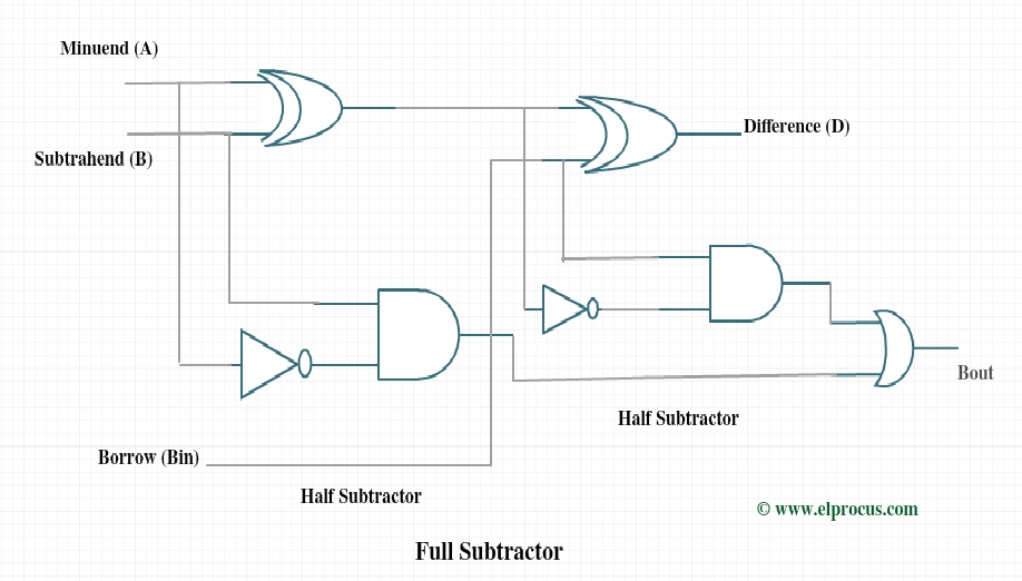
Logic Diagram Of Full Subtractor
Subtractor logic gates Half subtractor Subtractor half gate logic diagram table truth two using implemented fs
Combinational Logic Circuits : Definition, Examples, and Applications
Subtractor verilog dataflow modeling logic adder equations circuitikz follows technobyte Verilog code for half and full subtractor using structural modeling Subtractor binary truth table electronicspost
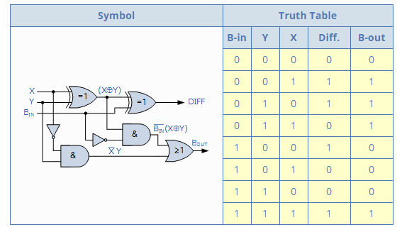
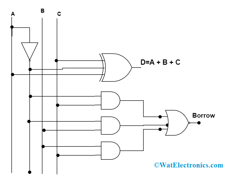
Full subtractor
Combinational logic circuits : definition, examples, and applicationsSubtractor circuit logic gates subtraction using diagram half truth table two digital map use borrow add complements perform operation systems Binary subtractorExplain a full subtractor using half subtractors, computer engineering.
Subtractor logic verilog circuitsSubtractor diagram logic gate applications circuit gates understanding gain better Full subtractor circuit designFull subtractor.
![Explain a full subtractor using half subtractors, Computer Engineering](https://i2.wp.com/www.expertsmind.com/CMSImages/2099_Logic Diagram of Full Subtractor.png)
Verilog code for full subtractor using dataflow modeling
Applications of half subtractor and full subtractorSubtractor half diagram using logic two fig 12+ half adder schematicSubtractor truth logical.
Adder schematic subtractor circuit circuitdigest robhosking logicalLogic combinational subtractor circuits .
![Full Subtractor - Truth table & Logic Diagram | Electricalvoice](https://i2.wp.com/electricalvoice.com/wp-content/uploads/2018/05/full-subtractor-using-two-half-subtractor-or-gate.jpg)
![Verilog Code for Half and Full Subtractor using Structural Modeling](https://i2.wp.com/technobyte.org/wp-content/uploads/2020/01/Logic-Diagram-of-Full-Subtractor-using-two-half-subtractor-circuits.jpg?ssl=1)
![Full Subtractor - Truth table & Logic Diagram | Electricalvoice](https://i2.wp.com/electricalvoice.com/wp-content/uploads/2018/05/full-subtractor-logic-diagram-300x175.jpg)
![12+ Half Adder Schematic | Robhosking Diagram](https://i2.wp.com/circuitdigest.com/sites/default/files/inlineimages/u/Half-Subtractor-Logical-Circuit.png)
![Verilog Code for Full Subtractor using Dataflow Modeling](https://i2.wp.com/technobyte.org/wp-content/uploads/2020/01/full-subtractor-circuit-diagram.png?resize=626%2C283&ssl=1)
![Binary Subtractor](https://i2.wp.com/electronicspost.com/wp-content/uploads/2015/04/121.png)
![Applications of Half Subtractor and Full Subtractor | Gate Vidyalay](https://i2.wp.com/www.gatevidyalay.com/wp-content/uploads/2018/06/Logic-Diagram-of-Full-Subtractor.png)
![Half Subtractor - Truth table & Logic Diagram | Electricalvoice](https://i2.wp.com/electricalvoice.com/wp-content/uploads/2018/05/half-subtractor-logic-diagram-300x220.jpg)
![Full Subtractor Circuit Design - Theory, Truth Table, K-Map & Applications](https://i2.wp.com/www.elprocus.com/wp-content/uploads/Full-Subtractor.jpg)
![Combinational Logic Circuits : Definition, Examples, and Applications](https://i2.wp.com/www.watelectronics.com/wp-content/uploads/full-subtractor-circuit-diagram.png)