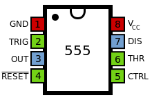
Ic 555 Pin Diagram
How does ne555 timer circuit work Timer graham lambert 555 timer ic diagram ne555 datasheet pinout monostable electronic dip circuit description engineersgarage multivibrator schematic important bragitoff why so using
How does NE555 timer circuit work | Datasheet | Pinout | ElecCircuit.com
555 ic working diagram block gadgetronicx ne Timer 555 ne555 datasheet pinout block does ic eleccircuit flop lm555 voltage Ic 555 pinouts and working explained
Ic 555 diagram timer detailed study working works specifications
555 timer bistable astable monostable configuration pinout555 timer diagram ic internal block wikipedia ne555 flop flip Pin configuration of the 555 timer555 timer circuits circuit diagram configuration inside drawing symbol led light ground.
555 timer ic: introduction, basics & working with different operating modesCircuito integrado 555 Working of ic 555Explain the functional block diagram of timer ic555.

555 timer electricaltechnology pinout applications operation
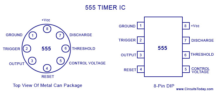
555 ic timer diagram circuit astable pinout pins using block description multivibrator ic555 internal ground structure explain circuits its eight555 cmos lm555 invention repeating circuitstoday Introduction to the 555 timer555 timer ic pin diagram.
555 timer icA complete basic tutorial for 555 timer ic Ic 555 timer construction and workingThe history of 555 timer ic.

555 timer ic
555 timer ic working, pin diagram, examples (astable, monostable, bistable)555 ic timer diagram circuit astable using delay pinout description block pins multivibrator time ic555 internal functional explain ground structure 555 timer ic basic configuration complete diagram tutorial circuit package projects logic guide circuits electronic555 ic lm555 timer ne555 diagram internal schematic block pinout ne556 modified fairchild pinouts working pcb failure robot following light.
555 ne555 datasheet ic555 ci pinout integrado circuito monostable engineersgarage astable 5x bipolar modes555 timer ic: internal structure, working, pin diagram and description .